Введение

In this guide it will be outlined on how to replace or disassemble an LCD screen display. A LCD screen usually needs to be replaced if it is not displaying the right coloration on the screen for example a yellowish tint. A LCD screen can also be replaced if it does not show anything at all.

  1. CqdRHbkTvDOS6sDQ
    CqdRHbkTvDOS6sDQ
    LTciYLhHLijeeaxm
    • Power the device down before taking any other actions.

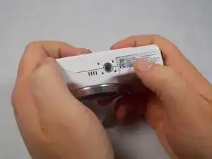
    • Hold the camera with the lens facing towards youself.

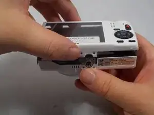
    • Turn the camera upside down and place your right thumb on the battery chamber cover.

  2. wpOXExkAxokYE5sk
    wpOXExkAxokYE5sk
    fVJJFyQgc3xoOg1j
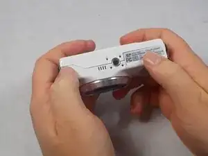
    • Hold the camera, then pull the battery chamber towards yourself with your right thumb.

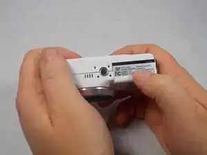
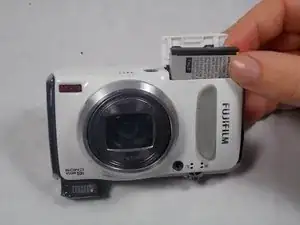
    • Pull the cover entirely out and release it to reveal the battery.

  3. StGrwmvQpVamD2TL
    StGrwmvQpVamD2TL
    JX12maROBbCFqmcc
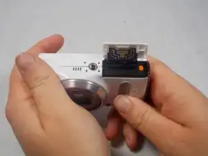
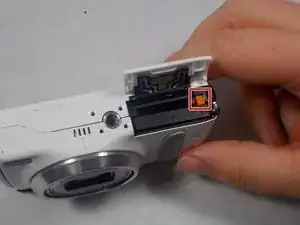
    • Locate the orange battery latch that holds the battery in place.

    • Use your finger to push the latch away from yourself to release the battery.

    • Remove the battery manually from the battery chamber.

    • Place the battery into a charger if it is dead.

    • Remove battery before performing any other repairs.

    • Replace defective battery if previous steps fail

    • Contact support on the Fujifilm website for further assistance

  4. ZcPZ4kyJZ5HaHfrQ
    ZcPZ4kyJZ5HaHfrQ
    ZPaL21yVMqdjTaoy
    bm12QprR6dl1sZaZ
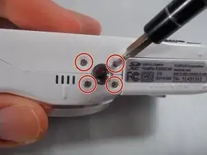
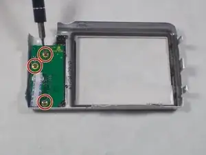
    • Remove four 2.5mm Phillips #1 screws on the bottom of the camera near where the camera mount attaches.

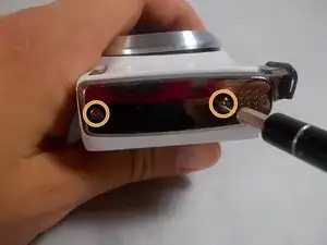
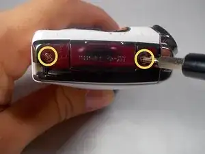
    • Remove two 5.1mm Phillips #1 screws on the left side of the camera relative to the LCD screen.

    • Remove two 5.1mm Phillips #1 screws on the right side of the camera relative to the LCD screen nearest to the mode wheel.

  5. 4mVqVivuEIe3tLFj
    4mVqVivuEIe3tLFj
    ipnXNsaQ65oSGOyA
    • Place the camera lens face down with the LCD screen face up on a flat surface, or hold it. Carefully lift the camera’s back cover approximately 1 inch.

    • Carefully lift the ribbon clamp connector back using the tweezers and remove the blue ribbon.

    • Do NOT pull on ribbon if the ribbon clamp connector still grasps the blue ribbon. This could cause severe damage to the ribbon.

    • If you are replacing the LCD monitor you can skip steps 6 and 7 for the selector button circuit board guide and go directly to the LCD monitor repair guide.

    • If you are replacing the Mode Dial you can skip steps 6 and 7 for the selector button circuit board guide and go directly to the Mode Dial repair guide.

  6. gBrvCrO3eC2kRWSd
    • Remove the back of the camera case and place it on a flat surface with the selector button circuit board facing up.

    • Remove the three 3.5mm Phillips #1 screws located on the chip seen in the image.

  7. 6VMLLgpLHFGH2Glg
    6VMLLgpLHFGH2Glg
    kvt6vV3RBmdgDRIF
    jTnOJbIYcfQdxSZS
    • Lift the chip with tweezers to remove it from the other remaining components.

  8. xhBytQtfILPuDTnk
    • With the LCD monitor facing upwards, use the tweezers to lift the ribbon clamp which will release the grip on the ribbon.

    • Failure to do this can result in major damage to the connection.

  9. GbZarYtbf6JhyKI5
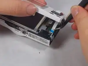
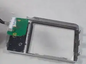
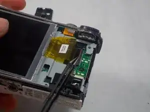
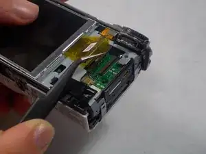
    • With the tweezers pull the ribbon away from the connector, freeing it and allowing it to move.

  10. Z2EaJmENiFndQdgY
    • With your fingers around the edges of the LCD monitor, lift it away from the camera.

Заключение

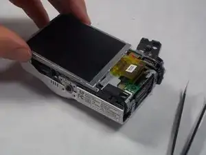
To reassemble your device, follow these instructions in reverse order.

Brittany Perkins

Участник c: 20/03/17

310 Репутация

0 комментариев