On our honor, we did this problem on our own, without looking at the solutions in previous semesters or other online solutions.
Problem Statement
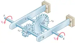
Under normal operating conditions a motor exerts a torque of magnitude at . Knowing that and the maximum allowable shearing stress is 10.5 ksi.
Determine the required diameter of member FH.
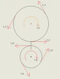
Shafts CE and FH with gears
Given
(4.1-1)
(4.1-2)
(4.1-3)
(4.1-4)
Soultion
Step One: Draw Free Body Diagrams
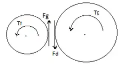
FBD of shafts
FBD of gears
For part A, by assuming constant velocity for the point of gear contact:
Step Two: Part "A" Analysis
The sum of the forces from the diagram equals zero
(4.1-5)
Isolating the torque in CE based on the applied torque,
(4.1-6)
(4.1-7)
Manipulating the stress formula the diameter can be determined,
(4.1-8)
Substituting the values given above, the diameter can be calculated
Step Three: Part "B" Analysis
(4.1-9)
Solving for the radius,
(4.1-10)
To get the diameter, multiply the equation of the radius by 2
(4.1-11)
Solving the Equation 4.1-11 with the values given, the diameter can be calculated
Problem 4.2 (Problem 3.25 in Beer, 2012)
On our honor, we did this problem on our own, without looking at the solutions in previous semesters or other online solutions.
Problem Statement
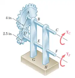
In the image below, there are two steel shafts, ABC and DEF, for which the maximum allowable shear stress is 8500 psi. They are connected by gears at A and D of given radii 4 in. and 2.5 in., respectively. There is a known applied torque at C, TC of 5 kips•in. and an unknown torque, TF, applied at F.
shafts AC and DF
a) Determine the required diameter of shaft BC
b) Determine the required diameter of shaft EF
Given
The magnitude of the torque at C,
Allowable shearing stress in the shafts,
Radius of the gear A,
Radius of the gear D,
Solution
Step One: Draw Free Body Diagrams
Bars ABC and DEFGears A and D
Step Two: Analysis
From the relation between the torques and the radius of the gears,
(4.2-1)
Therefore,
(4.2-2)
Now inserting the given values,
(4.2-3)
(4.2-4)
Step Three: Application
Part A
Allowable shearing stress in the shaft BC,
(4.2-5)
Where J for a solid circular shaft is
(4.2-6)
Insert the values and solve for the radius C.
(4.2-7)
(4.2-8)
(4.2-9)
Diameter of the shaft BC,
(4.2-10)
(4.2-11)
(4.2-12)
Part B
Allowable shearing stress in the shaft EF,
(4.2-13)
Insert the values and solve for the radius C.
(4.2-14)
(4.2-15)
(4.2-16)
Diameter of the shaft EF,
(4.2-17)
(4.2-18)
(4.2-19)
Contributors
Team Designee: Daniel Siefman
Table of Assignments
Problem Number
Solved by
Reviewed by
4.1
María José Carrasquilla, Joshua Herrera, Gregory Grannell, and Phil D Mauro
All
4.2
Tim Shankwitz, Andrew Moffatt, Michael Lindsay, and Daniel Siefman